
Solving yesterday's problems today
© 1999-2023 Jürgen Müller
juergen@e-basteln.de
Solving yesterday's problems today
© 1999-2023 Jürgen Müller
juergen@e-basteln.de
I don’t have step-by-step illustrated building instructions here. But with the sectional view of the PCB stack below and the following hints the build should be straightforward.
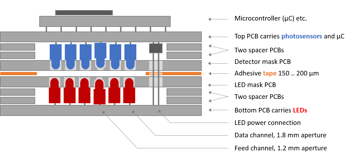
Sectional view of the stack of PCBs which make the chassis, as well as the key electronic components. For clarity, only 5 of the 8 data sensors and LEDs are shown.
The circuit boards and aperture boards for the detector and illumination are all made in one piece, to ensure that holes and milling contours align on all of them. (Probably an unnecessary precaution…) Hence you need to first break these boards apart, roughly clip off the tabs, and then sand the contours smooth. I recommend that you assemble the complete PCB package with screws according to the picture below and then sand it as a package to obtain even contours.
Please note that the fibers in PCB dust may be harmful, possibly carcinogenic. Work outside or in an area where you can contain the dust, and wear a protective mask. In Covid-19 times, at least we should all have FFP2 or N95 masks around…
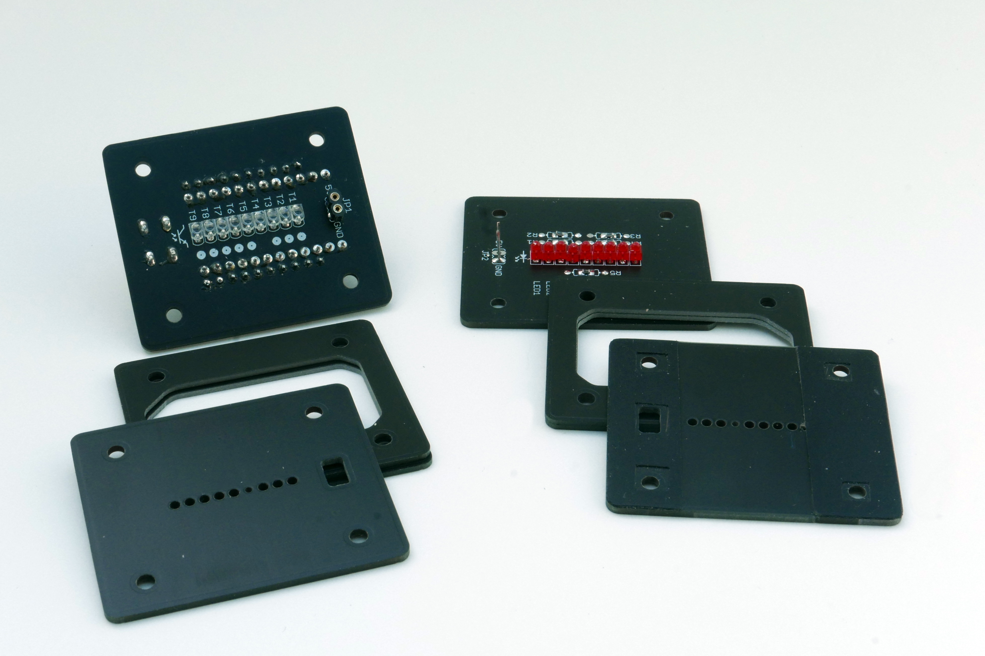
The stack of PCBs that make the paper tape reader.
The aperture hole for the feed track is only 1.2 mm in diameter, matching the feed holes in the paper tape for maximum signal modulation. On both aperture PCBs this hole needs to be drilled out to 1.8 mm to accommodate the LED and phototransistor, as indicated in the silk screen print on the PCB. But don’t drill all the way through – this must be drilled as a blind hole, preserving the 1.2 mm optical aperture! Use a drill press and/or much care to drill to the right depth.
To create a gap for the paper tape between the two aperture PCBs, two strips of adhesive tape are placed on top of the LED aperture board. This also provides lateral guidance for the paper tape, so you have to decide on a tape width you want to read. (I intend to provide inserts to reduce from 8-bit tape to 7 or 5 bit width, but have not tried this yet.)
Fix the aperture PCB to the work bench with a bit of adhesive tape, position a short piece of punched paper tape exactly over the apertures as a reference and attach it to the bench as well. Apply two strips of adhesive tape to the PCB, right next to the paper tape, as a spacer and guide. About 200 µm should be a good thickness; you may need to stack two layers of electrical tape or similar to get there. With a sharp knife, trim the tape along the PCB contours and cut the holes for screws and power connector.
To make it easier to introduce the paper tape into the narrow gap later, you can lightly sand the edges of the LED aperture PCB in the space between the two guide tapes. This creates a slight “funnel” for insertion of the paper tape.
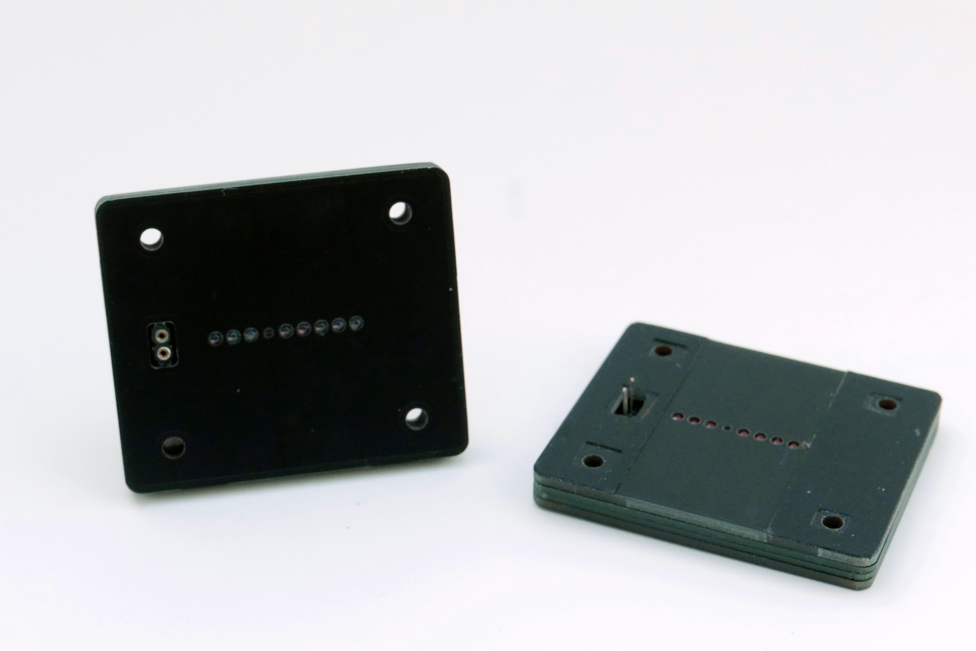
The pre-assembled modules: Phototransistor detector with apertures (left) and LED illuminator with apertures and spacer tape (right). Two sockets and wires provide power to the LEDs.
To populate the LEDs, insert all 9 loosely into the PCB. (Note the correct orientation – the body outline is shown on the silkscreen print.) Put the two spacer PCBs and the aperture PCB on top, wiggle the LEDs into their respective aperture holes, and hold the PCB stack together with screws or adhesive tape. Push the LEDs all the way down into their holes. The feed hole LED won’t go quite as far into its blind hole as the other LEDs. Then solder all LEDs.
Do the same with the phototransistors.
The LED series resistors (R1 to R5) can be populated as through-hole resistors inside the module. This requires resistors with a diameter less than 2.4 mm, the thickness of the two spacer PCBs. The diameters of through-hole resistors vary by manufacturer. If you cannot find suitably slim through-hole resistors, you can either mount them on the opposite side of the PCB, or you can populate 0603 or 0805 sized SMD resistors on the provided pads.
For the 5V power connection to the illuminator module, solder a two pin socket to the bottom of the detector board. (Make sure to get it reasonably straight.) Insert two clipped wire ends into the sockets. Provisionally assemble the full PCB stack while guiding the wires through their pads in the illuminator board. Clip wires to length and solder them to the illuminator board.
You can solder the Arduino Pro Micro permanently to the detector PCB with the square soldering pins provided with most Arduino boards. This will give the lowest-profile package. If that’s what you prefer, make sure that the phototransistors and 5V supply socket are soldered before you place the Arduino! Alternatively, use two rows of 1*12 pin sockets for the Arduino. In that case, the standard square pins will not fit, and you need to obtain smaller (turned) pin headers to match the sockets.
The resistor array RN1 (9 * 4.7 kOhm) can be soldered directly if you only want to read “real”, punched paper tape. Be sure to check the orientation – the common pin must be oriented towards the USB jack. If you want to use printed tape in the future, i.e. black dots on translucent paper, you may need to exchange RN1 for a 22 kOhm or 33 kOhm array to give higher light sensitivity. In that case, use a 1*10 pin socket for RN1.
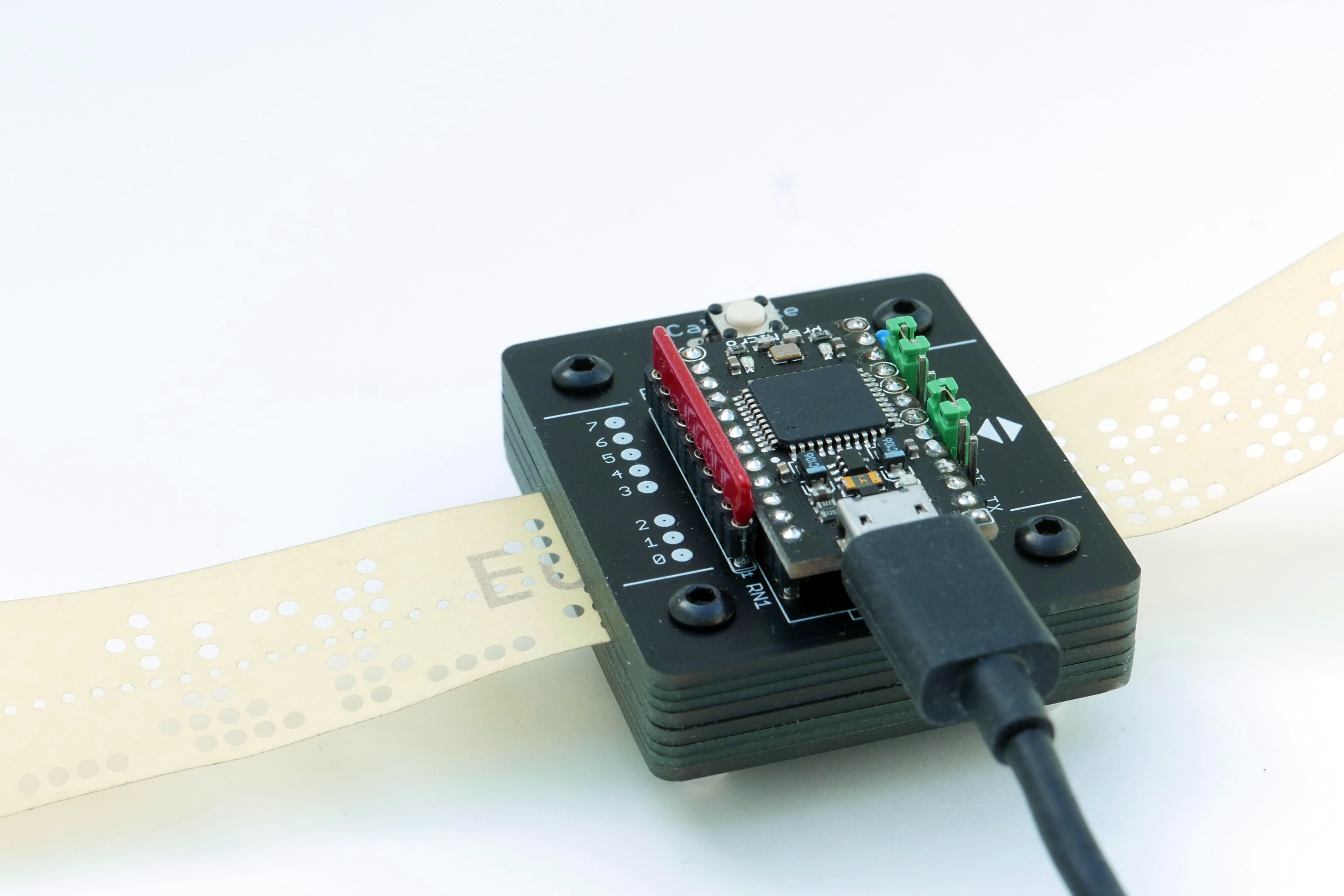
I opted for sockets for the resistor array (so I can try different values) and the Arduino (in case I need to get to the soldering joints beneath it).
The Pro Micro processor is programmed via the regular Arduino environment, via its Micro USB connection. Please find the source code for the paper tape reader in the Design Files section just below.
The Pro Micro board description is not pre-installed in the Arduino IDE. First, select File/Preferences from the main menu. In the dialog which opens, enter the URL below in the “Additional Board Manager URLs” field. Then select Tools/Board/Boards Manager and install the “SparkFun AVR Boards” package.
https://raw.githubusercontent.com/sparkfun/Arduino_Boards/master/IDE_Board_Manager/package_sparkfun_index.json
Again from the main menu, select Tools/Processor: ATmega32U4 (5V, 16 MHz). It is important to choose the right version! If you accidentally try to program a 5V a Pro Micro with the settings for the 3.3V version, you may brick it, requiring a reset. Connect the Pro Micro via USB, and set the right COM port via Tools/Port. Now you are ready to compile and upload the paper tape reader’s software!
Detector, illuminator and hole mask schematics and layout as EAGLE files, plus Gerber files for manufacturing. To be fabricated as a 1.6 mm thick PCB.
Spacer PCB EAGLE layout and Gerber files. To be fabricated as a 1.2 mm thick PCB. Four of these are needed for the paper tape reader.
PDF schematics and layout for pre-viewing.
Bill of materials with Reichelt part numbers and links. All parts are common and should be available from your electronics distributor of choice. Generic Pro Micro clones are cheaply available on ebay; the original Sparkfun version is significantly more expensive.
Arduino source code for Sparkfun/Arduino Pro Micro (ATmega 32U4), 5V/16MHz version.
Excel template to print your own paper tapes, if you do not have access to a tape punch. Print on thin paper, with Excel’s “adjust to page” option turned off in the printing dialog. To read these tapes, you will need to set the INV jumper (since ‘1’ bits are now represented by a darker spot instead of a transparent hole), and use a higher resistance array for RN1 (try 22 kOhm or 33 kOhm).