
Solving yesterday's problems today
© 1999-2023 Jürgen Müller
juergen@e-basteln.de
Solving yesterday's problems today
© 1999-2023 Jürgen Müller
juergen@e-basteln.de
This wristwatch displays the time on an original 1970s LED “bubble display”, as used in the early pocket calculators, and sports a beautifully prototypish breadboard look.
This is not my own design – the idea, circuit design, and firmware are by Inge P. from Norway. Inge has made a project description and his firmware source code and usage instructions available. Many thanks for a neat idea and implementation!
I just changed the build slightly, hiding the battery and charger right inside the breadboard instead of an additional 3D printed base. So this page has just a few photos, build notes, and the design files for my custom circuit boards.
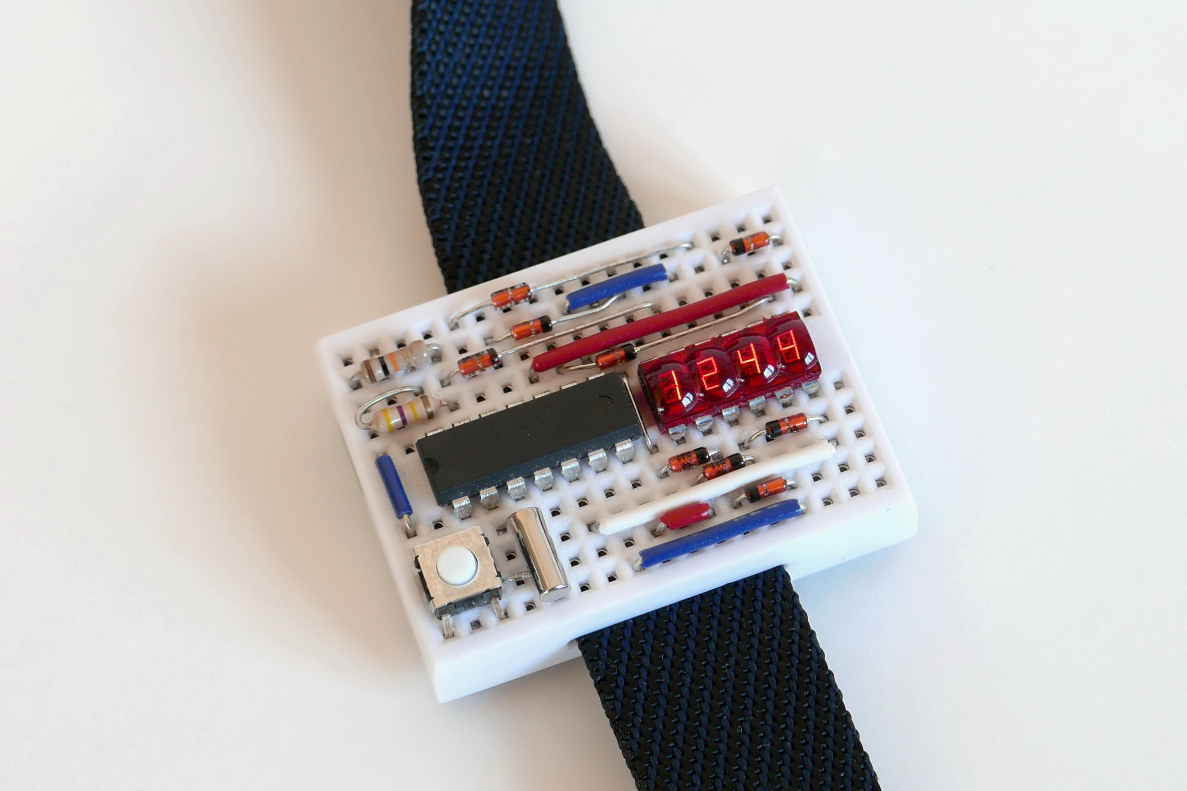
The fully assembled watch. I changed Inge's component layout slightly, to make room for an upright button in the lower left, where I find it easier to reach.
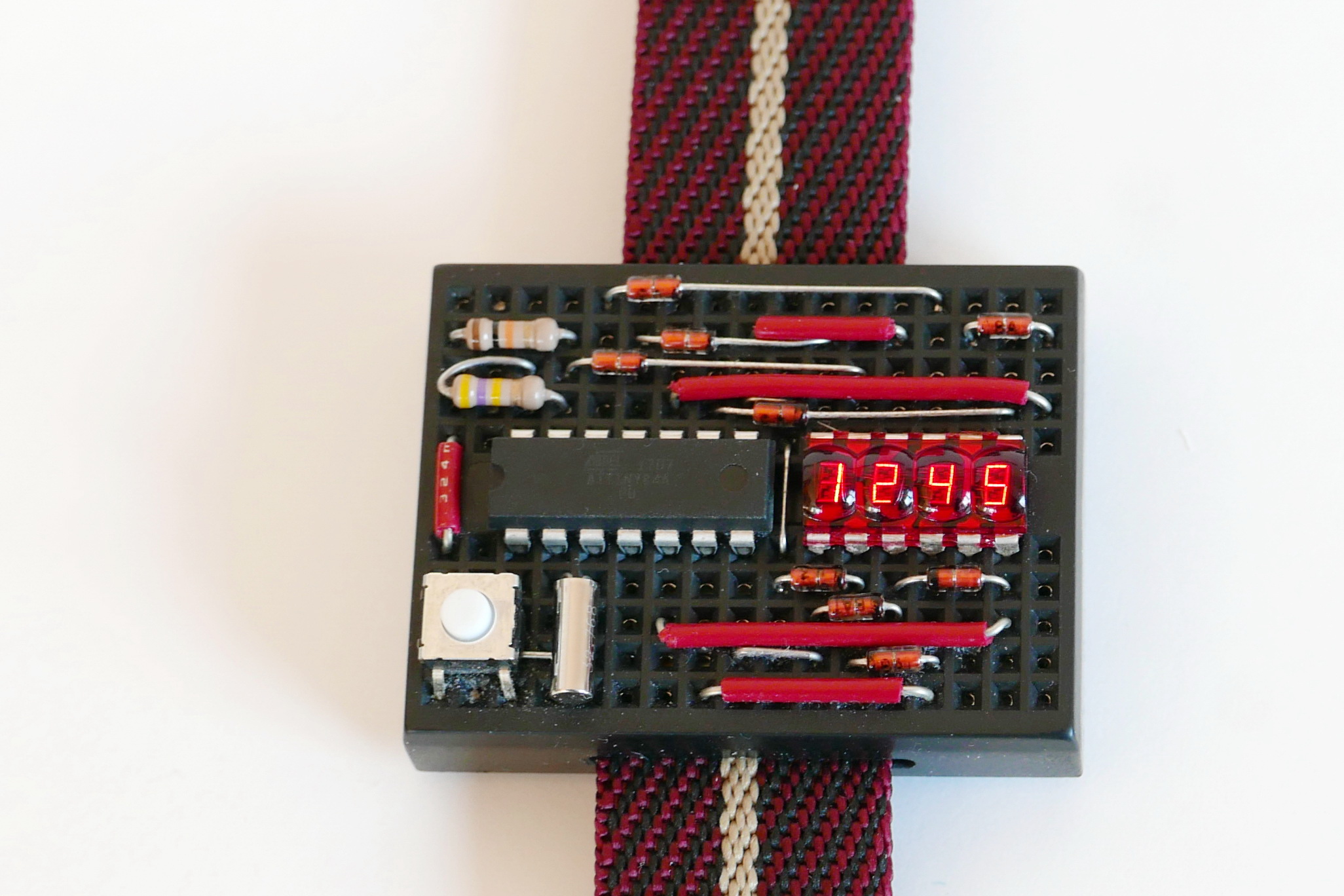
A black version, for the elegant nerd. ;-)
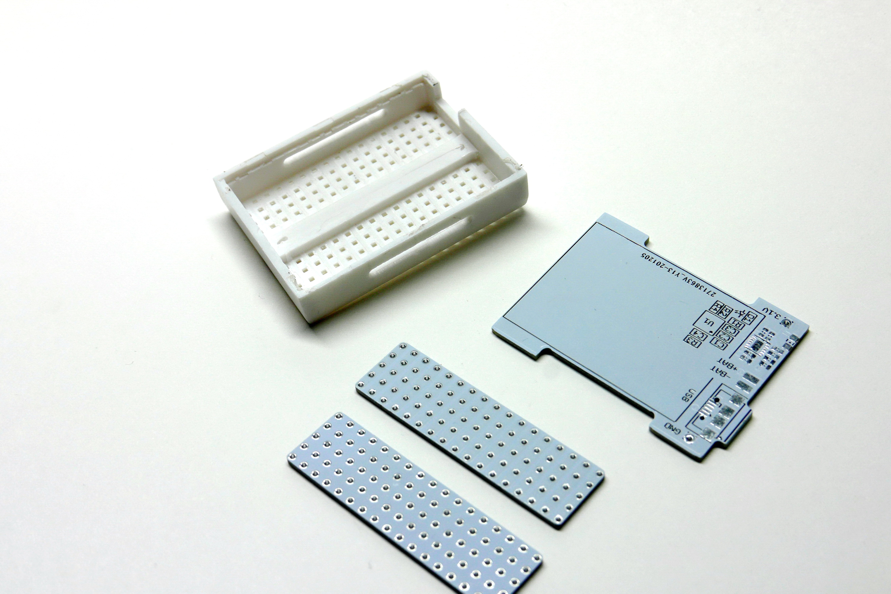
The breadboard is milled out to make room for the battery. A custom base board will carry a LiPo battery and charger; two small stripboards will replace the breadboard's contact springs.
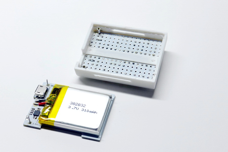
The assembled power supply, ready to plug into the populated breadboard.
The breadboard is a no-name product, available from various ebay sellers and other sources. 17 columns of 5+5 holes each, outside dimensions 45 * 34.5 * 8.5 mm³. Avoid the version with dovetail joints on the sides, and look for straight sides instead!
Mine came with double-sided adhesive tape on the bottom. After removing the tape, the contact springs are easily pushed out from above with a steel wire or thin nail. After milling away the inner plastic dividers which held the springs, the interior space measures 42.5 * 32 * 7.4 mm³. (Except for the rim running down the middle, which needs to stay a bit taller since there is a deep recess along its top. You get only 5.1 or 5.2 mm of clearance above it.)
To mill out the breadboard, I used a small bench drill press and two mini milling bits: a 3 mm end mill for most of the work, and a 2 mm bit for the wristband slits in the sides. The plastic is easy to mill, but needs to be removed in multiple steps – say 1 mm at a time – to avoid excessive lateral force which might break the plastic. A depth stop on the bench drill is highly recommended. For lateral positioning, I simply guided the breadboard by hand, helped by an adjustable stop rail.
When soldering components to the stripboards, clip their leads flush with the PCB before soldering. You want the completed joints to have the lowest possible profile, without sharp wire ends which could pierce the battery. Since the PCB through-holes are plated, stable solder joints will still be obtained. – The breadboard’s plastic melts easily, by the way; don’t touch it with the iron!
The ATtiny84A processor can be programmed in-circuit with a suitable programmer. Inge has reported that his AVRISP mkII programmer would only handle this after the LED display was disconnected from the PA6/MOSI pin – which is difficult to do once you have soldered everything onto the pseudo-breadboard. My AVR Dragon programmer does not have this limitation and can program the ATtiny fully in-circuit. Better test this on a real breadboard setup before you solder the chip!
SMD soldering of the power supply can be a bit tricky. The STNS01 charger IC comes in a small leadless package with solder pads largely below the IC, and the passive components are in 0402 size due to space constraints. I recommend ordering a stencil with the PCB to apply solder paste to the pads. I used a simple, manually controlled pizza oven for soldering, but a hot air iron should work as well.
The Lithium polymer battery can be up to 4 mm thick, 28 mm wide, and 38 mm long. I found 310 mAh batteries sized 3.9 * 28 * 35 mm³ on eBay which work nicely. They do however have a chip in their on-board battery protection circuit which actually stands slightly taller than the stated 3.9 mm. In my final builds, I mounted the battery with the offending chip oriented towards the base plate, and milled a shallow recess into the plate to accommodate the extra height.
One-piece Nylon wristbands are commonly offered as “NATO straps”. They come in a range of widths, 18 to 24 mm. The cutouts in the charger PCB (bottom plate) accommodate wristbands up to 22 mm; slits in the breadboard sides should be milled to the desired width. For my taste, a 20 mm wide strap looks best. Cheap ones are available on eBay; I like the adjustable version from WatchBandit which costs a bit more.
If you want to build you own breadboard watch, please start with Inge’s original project description and his firmware source code and usage instructions. The files below just add my alternate layout for the charger circuit (on a PCB which doubles as the base plate) and for the small stripboards which replace the breadboard’s spring clips.